Encoder Mounting Guide
How to Mount Encoders
Find the right method by shaft shape and measurement method
Hollow Shaft Encoder Mounting
A compact and clean direct-to-shaft mounting method for high-precision rotary measurement.
Shaft Type Encoder Setup
A flexible installation option for coupling-based measurement when direct hollow shaft mounting is not suitable.
Find by Shaft Shape and Measurement Method
Measure by Direct Shaft Mounting
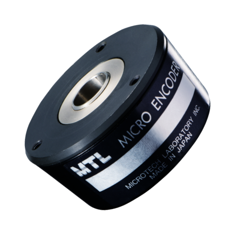
Hollow Shaft Type
MEH, MAH Series
Enables high-precision rotary measurement. Ideal when installation space is limited.
View details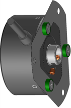
Simplify Hollow Shaft Installation
Set Screw Fixed Type
Direct mounting to the machine shaft with set screws enables easy, high-precision, space-saving rotary measurement.
View details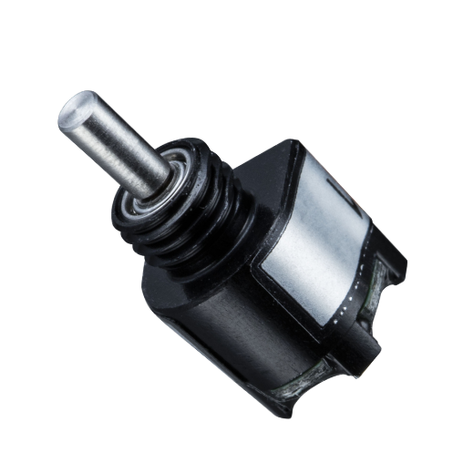
Measure Rotation with a Coupling
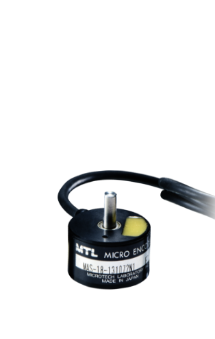
Shaft Type
MES, MAS Series
Choose the best model from a wide range of resolutions, outer diameters, and shaft lengths. Couplings are also available as an option.
View details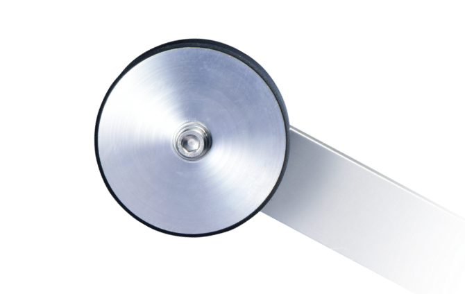
Measure by Pressing a Roller Against the Target
Roller Encoder Series
Using a roller with a 200 mm circumference, length measurement is possible with resolutions from 1 mm to 0.1 mm.
View details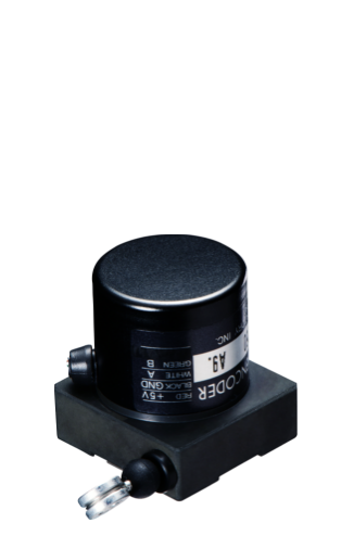
Digital Linear Measurement for Retrofit Applications
Wire Encoder Series
No linear guide rail is required, making stroke measurement easy. Digital display is also possible when used with a counter.
View detailsWatch the Hollow Shaft Encoder Mounting Method, MEH, MAH
Mounting Procedure
-
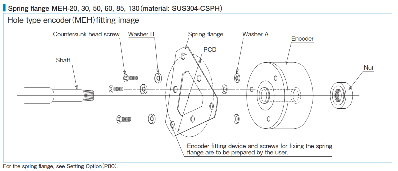
Attach the spring flange to the encoder
Mount the optional spring flange to the PCD mounting holes on the encoder base using the included flat-head screws, washer A, and washer B. -
Insert the encoder onto the measured shaft
Machine the measured shaft with a stepped section and a male thread at the tip, then insert the encoder so that the hollow shaft end face contacts the stepped surface. -
Clamp and secure the rotating shaft with a nut
Clamp the hollow shaft in the thrust direction using a nut.
Before fully tightening, rotate the encoder shaft lightly and tighten it at the position with the least runout. -
Fix the spring flange to the machine frame
Finally, use the mounting holes on the outer side of the spring flange to secure it to the machine frame. Screws for fixing to the frame are not included.
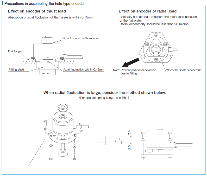
When fixing it to the frame, use a spacer of 2.5 mm or more between the spring flange and the frame so that the spring flange does not touch the frame. This is necessary to maintain the flange spring function.
Important Notes for Hollow Shaft Encoder Assembly
Because the spring flange is a flat plate, it is difficult for it to absorb load caused by radial eccentricity. Please keep radial eccentricity to approximately 20 μm or less during rotation.
If radial fluctuation is large, we can also provide a special spring flange.
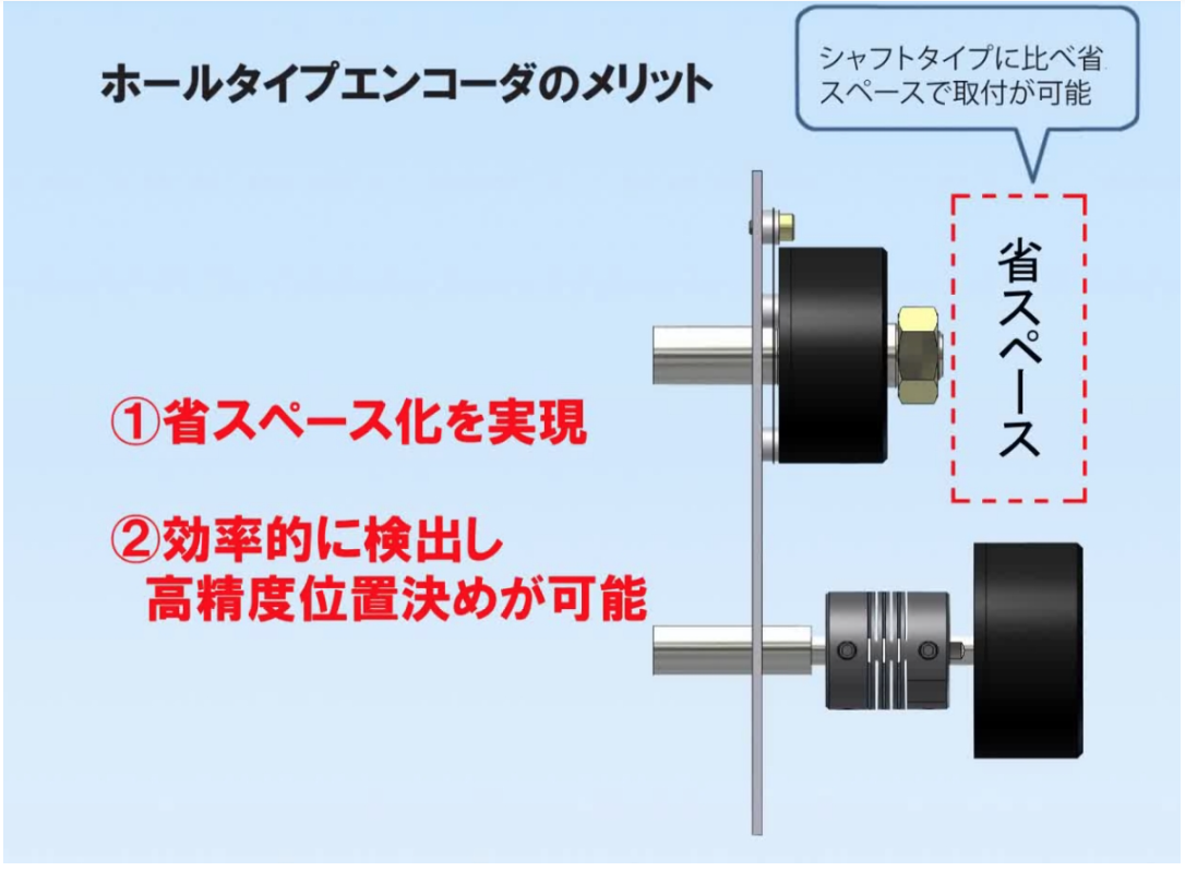
Advantages of the Hollow Shaft Type
High-precision detection
This hollow shaft design can be mounted directly onto the measured shaft. Unlike shaft encoders, no coupling is required, and the encoder can be mounted in a way that fits the machine. This reduces mechanical error and enables highly accurate reading of shaft rotation.
Space saving
Because it can be mounted directly to the mating shaft, the number of mounting parts can be reduced. Since no coupling is required, axial space can also be saved.
Cost reduction
Simplifying the mechanical structure helps reduce the total machine cost.
Related Encoder Options
Set Screw Fixed Encoder
Useful when you want easier hollow shaft installation with compact, practical mounting.
View details
Wire Encoder Series
A good choice when direct rotary installation is difficult and linear stroke measurement is needed instead.
View detailsShaft Type Encoder, MES and MAS, Mounting Method
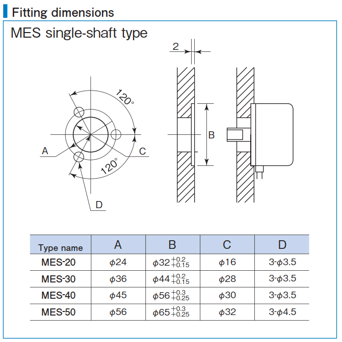
Please use this when the main body base cannot be mounted from the shaft side on the single shaft of MES-20 or MES-30.
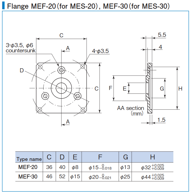
Flange, MEF-20 for MES-20, MEF30 for MES-20
Mounting Dimensions
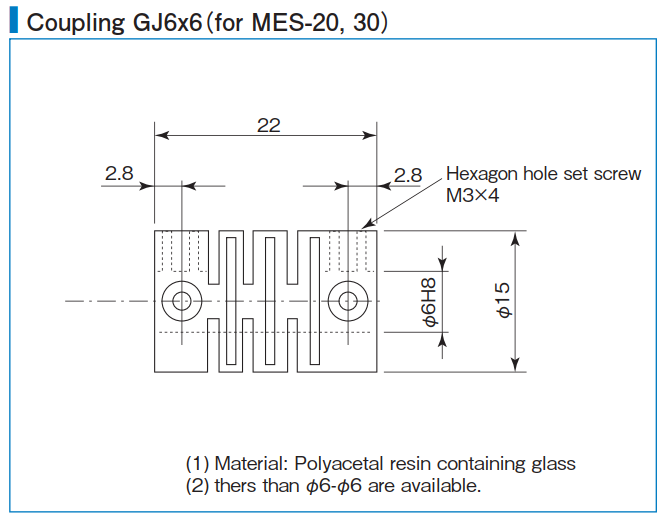
Coupling GJ6×6, for MES-20 and MES-30
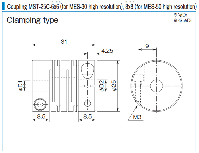
Coupling MST-25C-6× for MES-30 high resolution, 8×8 for MES-40 and MES-50 high resolution
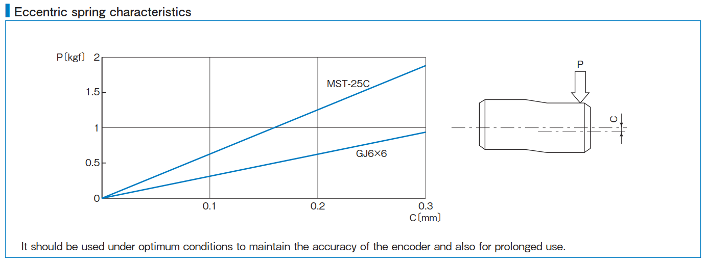
Eccentric Spring Characteristics
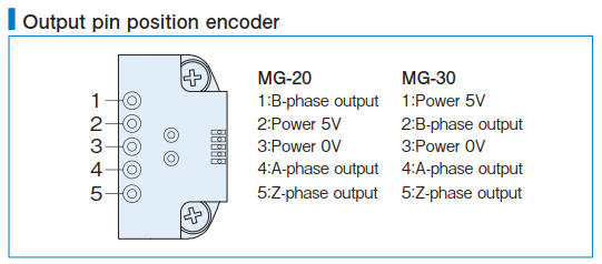
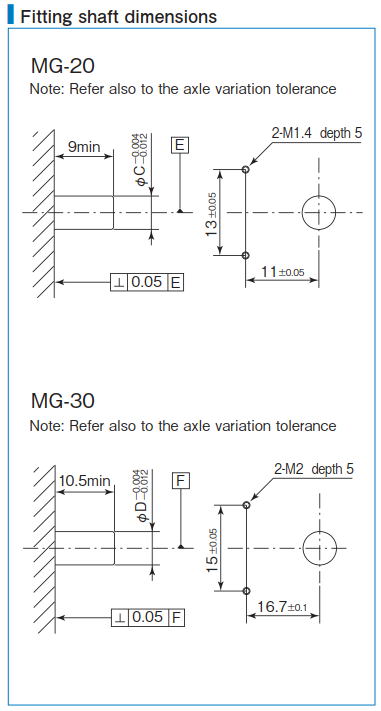
Module Encoder, MG Series, Mounting Method
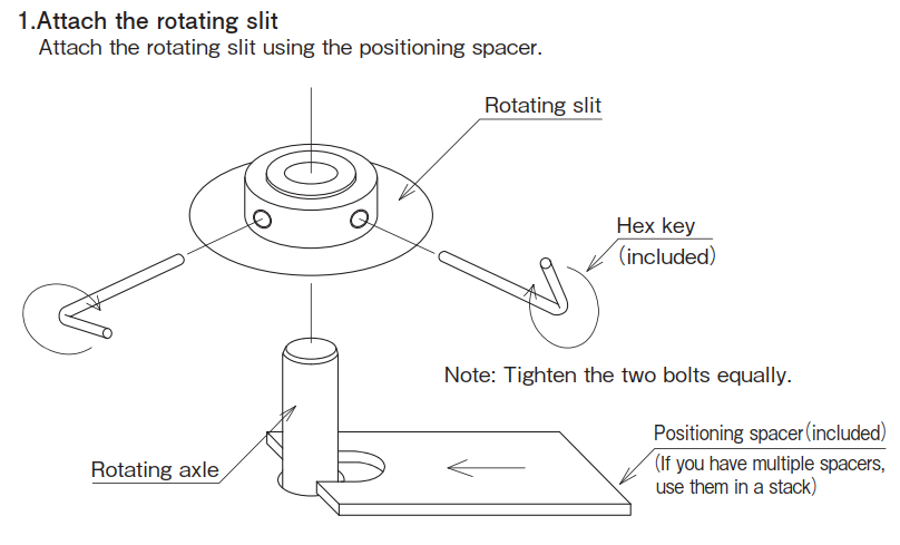
Rotating Slit Disk
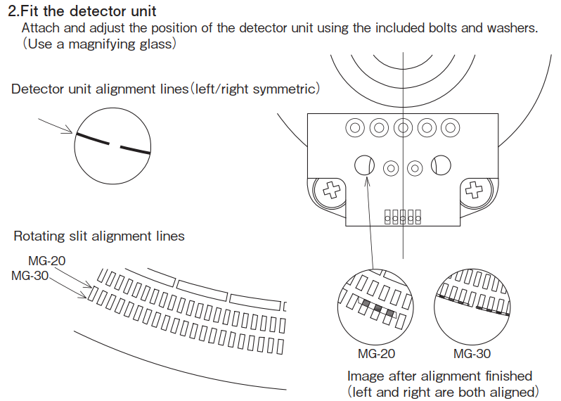
Detection Unit
Mounting Dimensions and Allowable Variation
Wiring Pins