
エンコーダとは
What Is a Rotary Encoder
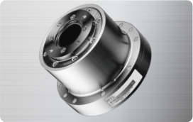
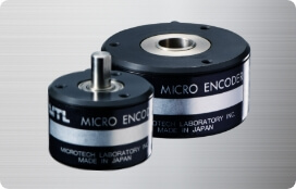
About MTL Rotary Encoders
A rotary encoder is an electronic device that converts rotational or linear motion into signals used to detect direction, displacement, and angle.
MTL encoders are used with motors and across many other applications. Our products are integrated into a wide range of equipment and systems in multiple industries.
Applications
From everyday equipment to specialized systems.
-

Elevator speed control and floor leveling
-

Roller speed control in industrial printers
-
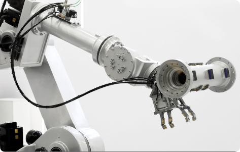
Integration with ultra-compact industrial actuators
-
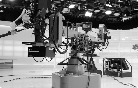
Broadcast camera systems
Encoder Types
Used across general and advanced applications.
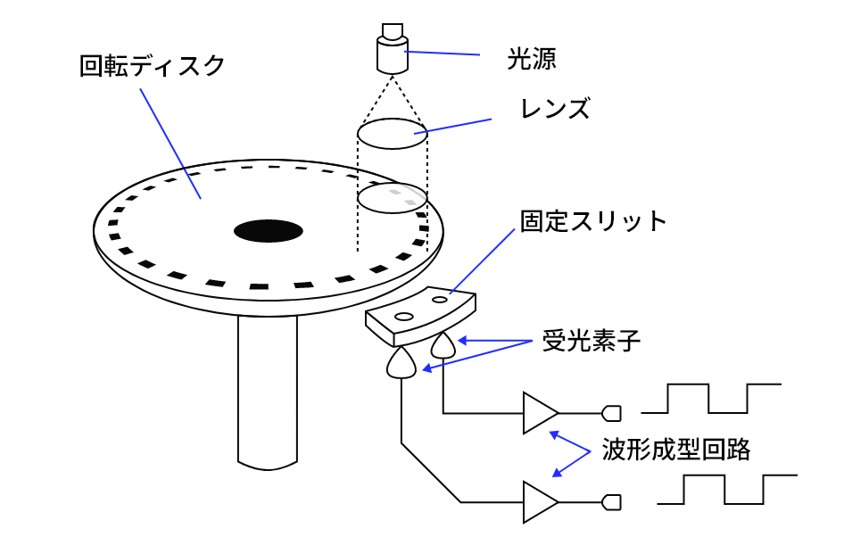
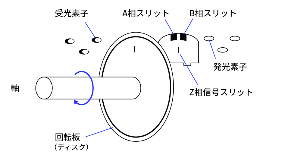
Incremental
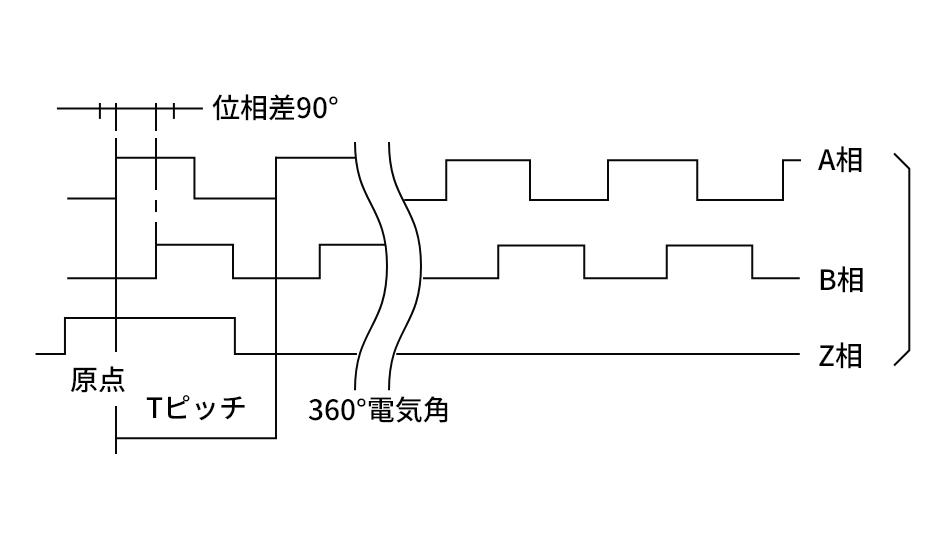
Incremental encoders use a disk with evenly spaced slits. Two photo-detectors output phase-shifted signals (A and B). A controller calculates rotation by adding or subtracting counts based on the direction derived from A/B phase. If pulses are missed or miscounted, the error remains until an index or reference is applied.
Structure
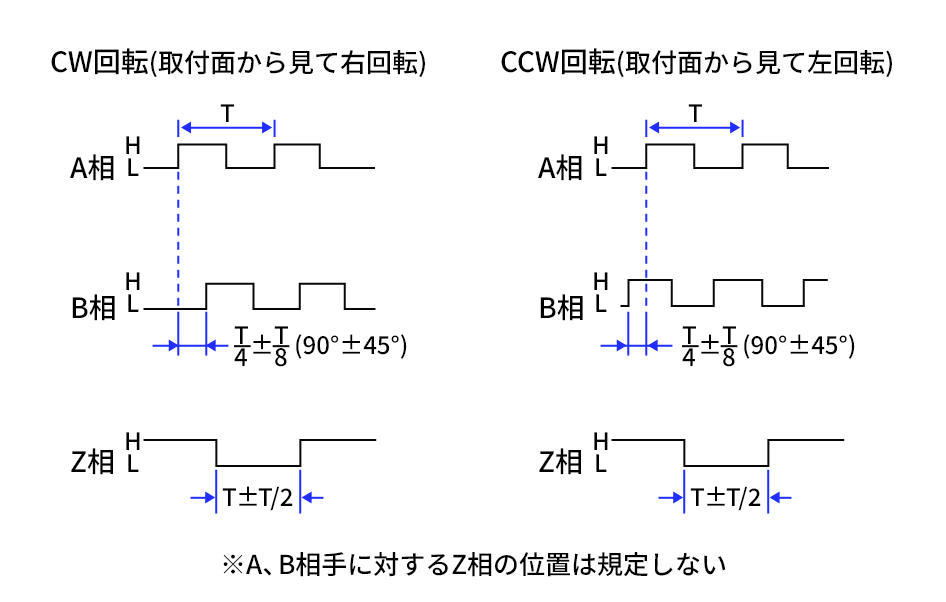
Output Waveforms
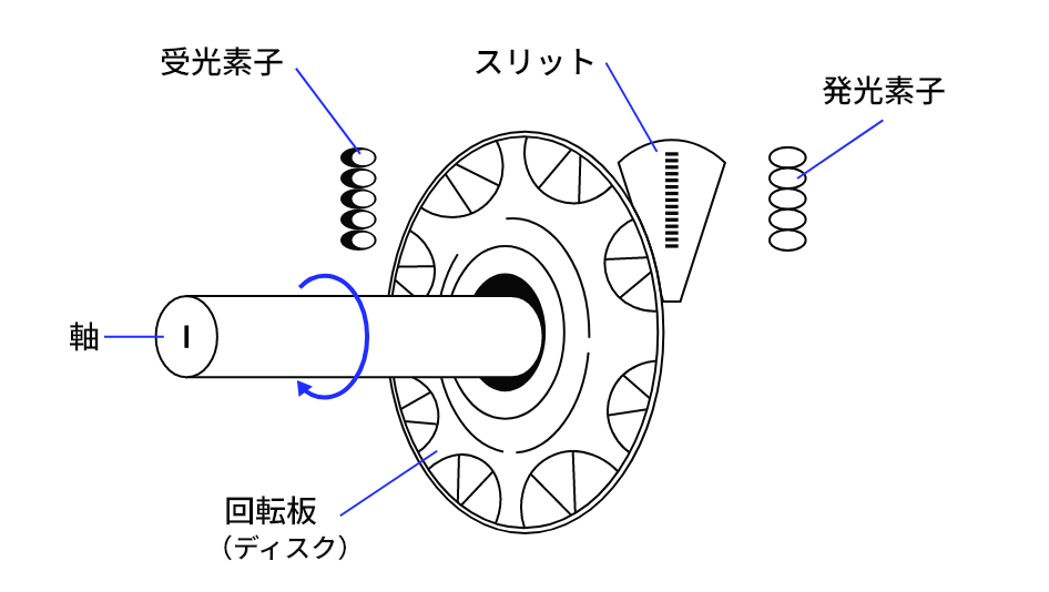
Absolute
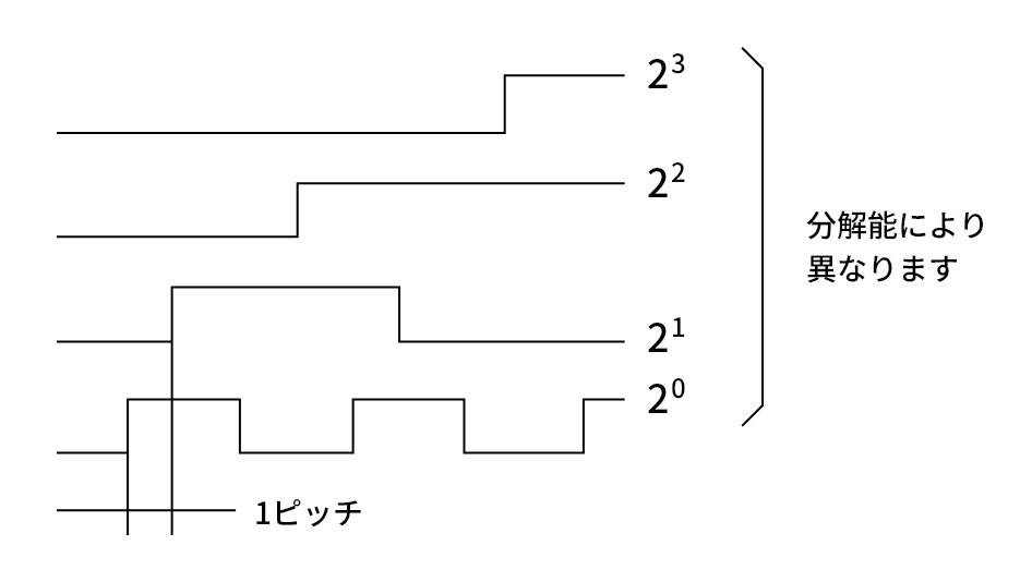
Absolute encoders assign a unique code pattern to each position on the disk and output an absolute angular position independent of motion history. They are robust against noise, but achieving higher resolution generally requires more bits.
Coding schemes include binary and Gray code. Binary can switch multiple bits at boundaries, which can increase read errors. Gray code changes only one bit between adjacent positions, so a single-bit misread causes at most an adjacent position error. For this reason, Gray code is commonly used in absolute rotary encoders.
Structure
Output Waveforms
CONTACT
Request a product demo or a quotation. Feel free to contact us.
Incremental Output Circuits and Waveforms
Used across general and advanced applications.
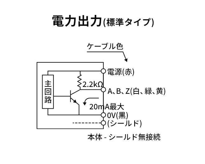
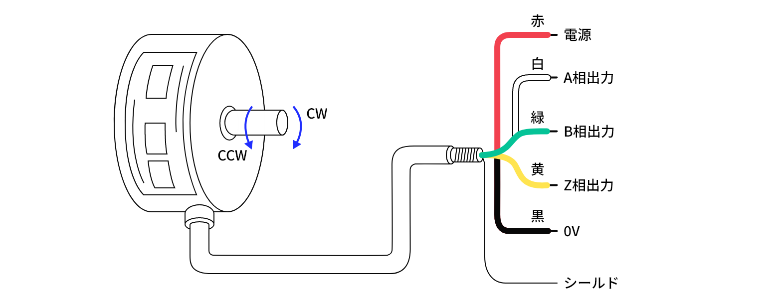
Supply voltage: DC 5–12 V or fixed 5 V / 12 V
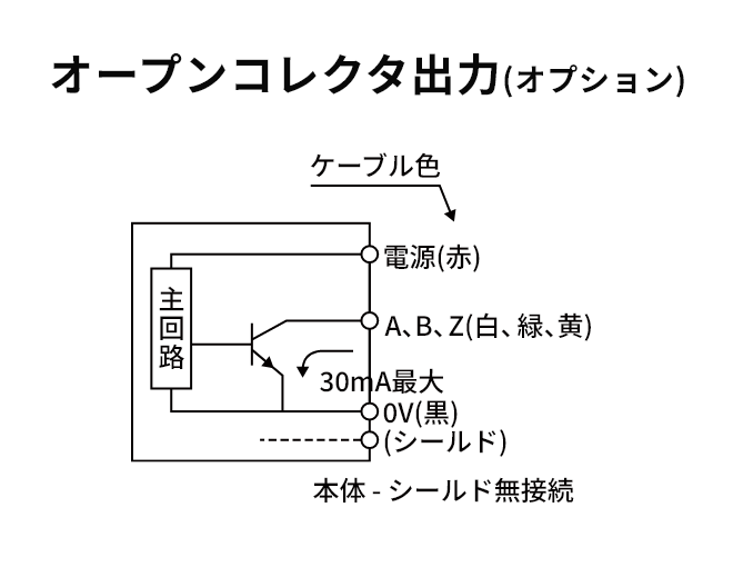
Supply voltage: DC 5–12 V or fixed 24 V
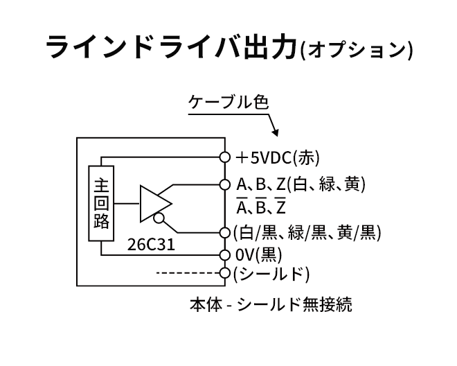
Supply voltage: DC 5 V, current consumption ≤150 mA
*For long transmission distances, ensure the input end of the encoder cable receives the specified voltage.
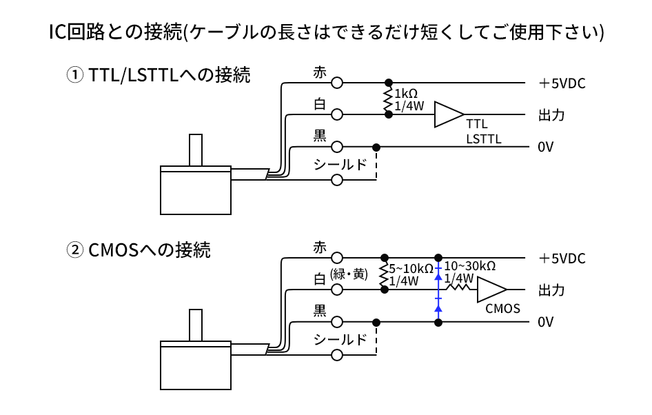
Output Circuit Diagram
Connection Example
Long Service Life
The LED light source typically defines encoder service life (about 10 years). External conditions may cause failures.
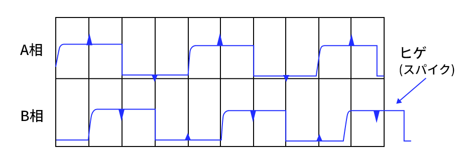
On rectangular (TTL/CMOS) outputs, small spikes may appear on the flat parts of the waveform depending on cable length. This results from stray capacitance between signal lines. Switching on A or B can induce a transient on the other line.
For example, when A is high, the rising edge of B can create a transient above A’s high level. When A is low, the falling edge of B can create a transient below A’s low level. If these transients remain outside the logic thresholds of the system, they are not an issue.
Counting typically increments when A=H then B=H. Brief chatter on A alone does not increment counts. To reduce spikes, use a smaller load resistance, shorten the cable, choose low-capacitance cable, and connect the cable shield to 0 V to help suppress noise.
For better noise immunity, connect the encoder cable shield to FG (earth). We also recommend grounding the customer-side PCB to FG, unless FG is a noise source in your system.
Common Causes of Failure
01
Reverse polarity (Vcc/GND)
Wiring mistakes or incorrect connector mating can reverse power polarity. Please have qualified personnel perform connections.
02
Overvoltage
Use a regulated power supply within the specified range. Route wiring to minimize noise coupling from other equipment.
03
ESD / surge noise
Our ESD countermeasures include:
- Antistatic workwear
- Antistatic footwear
- ESD-grounded mats on workbenches
- ESD panels at factory entrances
- ESD wrist straps
- Use of ionizers
04
Shorts between signal lines
Shorts can prevent proper pulse detection. This often occurs with unused or floating wires. Please check all cable terminations carefully.


In Case of Malfunction
We can investigate defective products to determine the cause and whether repair is possible.
Please feel free to contact us for more details.