Multi-Angle, High-Accuracy Imaging “JIGEN”, High-Speed Tiled Inspection System
Application Case: Tiled Imaging Inspection
This case shows how a direct drive θ axis and tilt axis help tiled imaging inspection. The goal is simple: move fast, stop accurately, and keep the image stable.
Challenge
Large parts need throughput. The hard part is stopping in the same place every cycle so the captured images stay consistent.
Tiled imaging repeats “move, stop, capture” many times. Position variation and slow settling show up as stitch error, blur, or unstable inspection results.
μDD Motor Benefits
Direct drive removes belts and gearboxes from the axis. This reduces backlash and reduces elastic flex in the drivetrain. That supports repeatable stops and faster settling before capture.
| What the system needs | Where direct drive helps |
|---|---|
| Repeatable stop position | Backlash free motion reduces shot to shot position variation. |
| Short settling after indexing | Fewer mechanical parts reduce compliance and reduce settling scatter. |
| Stable capture | Less drivetrain flex reduces bounce that affects the camera and lighting. |
| Clean routing | Hollow shaft routing keeps wiring and plumbing simple. |
Motor Selection
Use this checklist to narrow down the motor quickly.
| Selection item | What to confirm | Why it matters |
|---|---|---|
| Indexing pattern | Move angle, stop count per part, dwell time | Stop and go motion exposes settling issues fast. |
| Acceleration | Payload inertia, fixture inertia, target tact time | Faster indexing only helps when the axis settles before capture. |
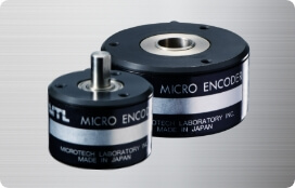
| Encoder resolution | Stitch tolerance and pixel scale | Match resolution to the inspection tolerance you need. |
| Hollow shaft | Cables, air lines, lighting cables, vacuum lines | Plan routing early. It prevents rework later. |
| Space limits | Outer diameter, motor height, mounting stack | A compact stack keeps the structure stiffer. |
| Stiffness | Base plate thickness, bracket stiffness, bearing support | Stiffness sets settling time. A flexible base slows everything down. |
How to verify: run a fast move, then capture images immediately after the stop. Check how soon the image becomes stable enough for inspection.
System Example
This video shows a concept mechanism for image inspection of large electronic components around 150 mm (W) × 100 mm (D) × 50 mm (H). Large parts need tiled imaging because field of view and resolution limit a single shot.
At high tact, residual vibration affects the optical system. Motion design and structure stiffness decide whether the system settles fast enough for reliable capture.
Motor Used
| Model name | Product | Key specs (reference) | |
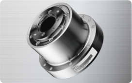
| 1 | MDH-7006-12960E (θ axis) | Low profile hollow shaft direct drive motor |
Outer diameter: φ70 mm, hollow bore: φ25 mm Resolution: 51,840 counts/rev Peak torque: 1 Nm |
| 2 | MDH-7018-12960E (tilt axis) | Compact hollow shaft direct drive motor |
Outer diameter: φ70 mm, hollow bore: φ25 mm Resolution: 51,840 counts/rev Peak torque: 3 Nm |
Integration Notes
- Tune for settling: the axis must settle before capture.
- Build it stiff: if the base flexes, the optics see it.
- Route cables early: confirm bend radius and strain relief through the hollow shaft.
- Judge with images: use real capture tests, not only encoder logs.
Reference system: VISCO Technologies Corporation (concept mechanism)
https://www.visco-tech.com/product/concept/jigen/
Contact
Send us your payload size, target tact time, and available space (outer diameter, height, hollow bore). We will recommend a direct drive motor for your θ axis or tilt axis and share integration notes based on your layout.