KEYENCE KV-8000 PLC and MC-200 Connection Guide
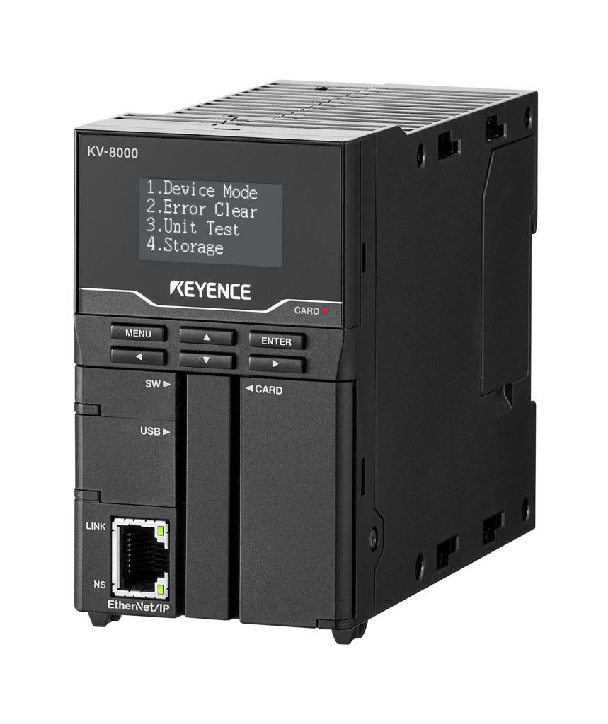
KEYENCE KV-8000 PLC and MTL MC-200 Connection Guide
This page explains the basic configuration for connecting a KEYENCE KV-8000 Series PLC to an MTL MC-200-7220A servo driver.
The standard configuration uses a positioning unit to send pulse train commands from the PLC to the MC-200 driver. Additional units may be required when the PLC must receive encoder signals, absolute position data, or motor operating information.
Page contents: Overview | Compatible Driver | Required PLC Units | Unit Selection | Connection Diagram | Setup Checklist | Contact
Connection Overview
The KEYENCE KV-8000 Series can control the MC-200-7220A using pulse train position commands.
The PLC positioning unit sends command pulses to the driver. The MC-200 then controls the connected μDD Motor according to the configured command format, electronic gearing, acceleration, speed, and position settings.
The required KEYENCE units depend on the signals that must be exchanged between the PLC and the MC-200 driver.
- Pulse train position commands require a positioning unit.
- Incremental encoder feedback requires a compatible high-speed counter input.
- Absolute position data requires a compatible RS-422 serial communication interface.
- Motor current, speed, or position-error monitoring may require an analog input unit.
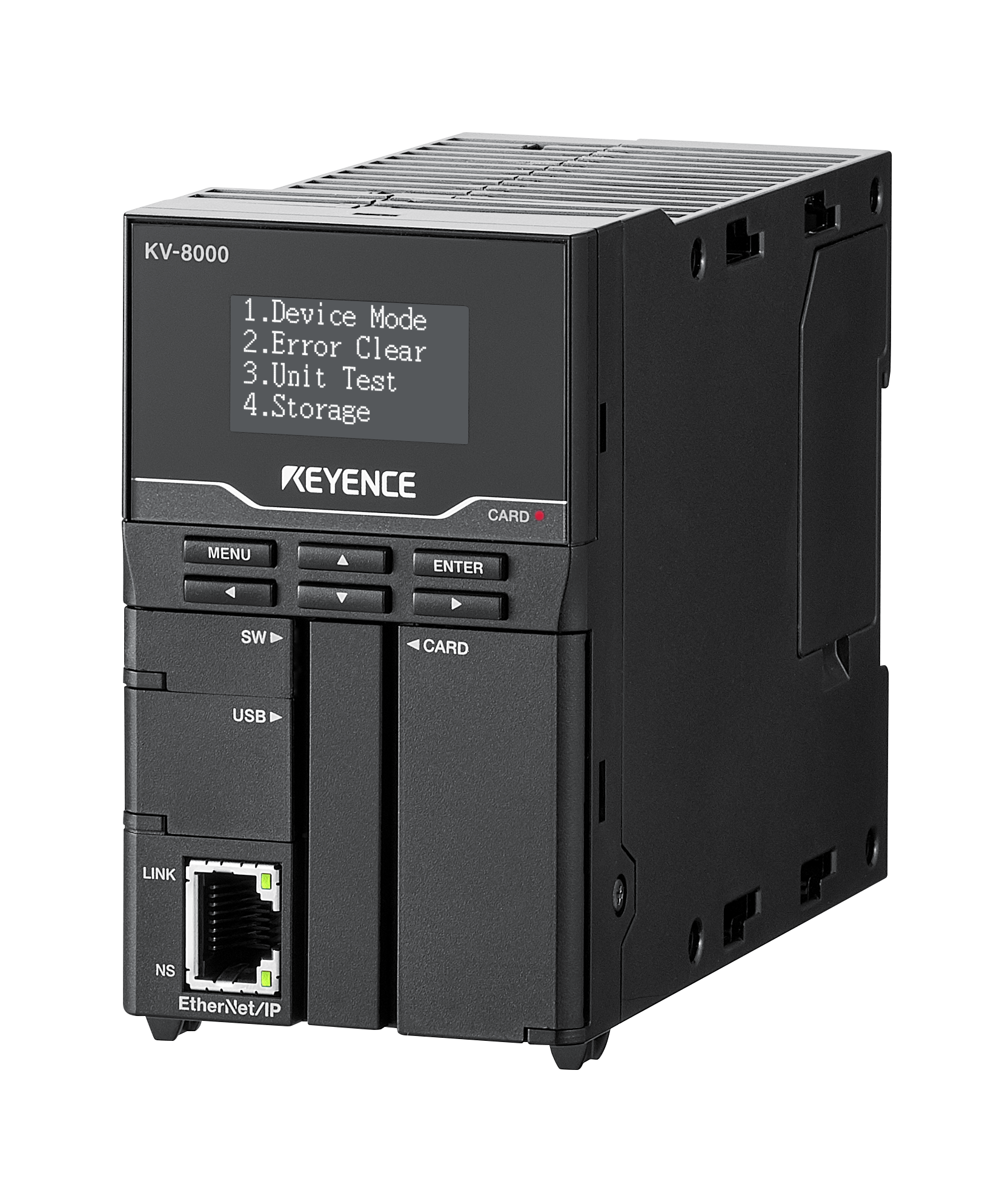
KEYENCE product information: KV-8000 Series
Compatible MTL Servo Driver
MC-200-7220A
The MC-200-7220A is the digital and analog I/O version of the MC-200 Series servo driver. It can receive pulse train commands from a PLC positioning unit.
Supported pulse command formats include:
- Pulse and direction
- CW and CCW pulse commands
- Two-phase quadrature pulse commands
Important: The pulse output frequency configured in the KEYENCE PLC must remain within the maximum pulse input frequency specified for the MC-200 driver.
View the MC-200 Series servo driver
Required KEYENCE KV-8000 Units
High-Speed Positioning Unit
Model: KV-SH04PL
The KV-SH04PL sends pulse train position commands from the KV-8000 PLC to the MC-200-7220A.
This unit is required when the MC-200 is controlled using external pulse commands.
The pulse output circuit, signal common, command format, and maximum frequency must be configured to match the MC-200 input specifications.
High-Speed Counter Unit
Model: KV-SSC02
The KV-SSC02 may be used when the PLC must receive incremental A-phase, B-phase, and Z-phase encoder signals from the MC-200 system.
This unit is not required when the PLC only sends commands and does not need an independent encoder count.
Before wiring, confirm the encoder output circuit, signal voltage, maximum response frequency, counting mode, and line receiver requirements.
Serial Communication Unit
Model: KV-XL402
The KV-XL402 is an RS-422A and RS-485 serial communication unit. It may be used when the PLC must receive absolute position data output from the MC-200 driver.
Before implementation, confirm the MC-200 communication format, baud rate, data length, ASCII or binary format, wiring, termination resistance, and PLC receive program.
This unit is not required when the PLC does not need absolute position information.
Analog Input Unit
A compatible analog input unit may be added when the PLC must receive the MC-200 analog monitor output.
Depending on the driver settings, the analog monitor can be used to observe information such as motor current, speed, or position error.
Confirm the selected monitor function, output voltage range, scaling, signal common, and analog input specifications before connection.
KEYENCE Unit Selection
| Required Function | Recommended Unit | Purpose | Requirement |
|---|---|---|---|
| Send position commands by pulse train | KV-SH04PL | Outputs pulse commands to the MC-200-7220A | Required for pulse control |
| Read incremental A/B/Z encoder signals | KV-SSC02 | Receives incremental encoder feedback | Optional |
| Read absolute position data through RS-422 | KV-XL402 | Receives serial absolute position data | Optional |
| Read motor current, speed, or position-error monitor signals | Compatible analog input unit | Receives the selected MC-200 analog monitor voltage | Optional |
Basic Signal Flow
Position Command
KEYENCE KV-8000 PLC → KV-SH04PL positioning unit → MC-200-7220A pulse command input
Incremental Encoder Feedback
MC-200 A-phase, B-phase, and Z-phase output → KV-SSC02 high-speed counter unit
Absolute Position Data
MC-200 RS-422 position output → KV-XL402 serial communication unit
Motor Operating Monitor
MC-200 analog monitor output → compatible KEYENCE analog input unit
Connection Diagram
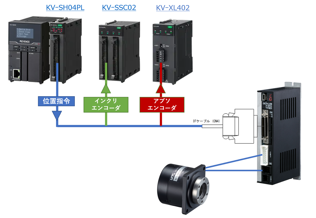
The diagram is provided as a configuration reference. Confirm the latest pin assignments, signal voltage, signal common, connector specifications, shield termination, and FG connection in the applicable KEYENCE and MTL documentation before wiring.
KV-SH04PL Positioning Unit Reference

Setup Checklist
Confirm the following items before starting the system:
- μDD Motor model number
- MC-200 driver model and firmware version
- Incremental or absolute encoder configuration
- Pulse command format
- Pulse output circuit and input circuit compatibility
- Maximum pulse frequency
- Electronic gear and command-pulse scaling
- Servo ON, alarm reset, in-position, and alarm signal assignments
- Origin sensor and Z-phase homing method
- Signal common and power-supply wiring
- Shield and FG connection
- RS-422 format and termination when using absolute position data
- Analog monitor scaling when reading current, speed, or position error
Engineering note: PLC unit selection alone does not guarantee electrical or communication compatibility. Confirm the complete system using the latest MTL driver specifications, KEYENCE unit manuals, encoder configuration, and actual wiring design.
Confirm Your KV-8000 and MC-200 Configuration
Please provide the μDD Motor model, MC-200 driver model, encoder type, required PLC commands, required feedback signals, pulse frequency, and application details.
MTL will review the proposed configuration and confirm the required interface, wiring points, and technical documentation.