Micro Encoder FAQ

About Micro Encoders
Mainly the optical detection method.
Using an LED as the light source, the encoder detects electrical signals with a light-receiving element based on the light and dark pattern passing through the rotating slit disk.
Other detection methods include magnetic, Hall element, electrostatic, electromagnetic induction, and resolver types.
The main difference is whether homing is required.
An incremental encoder outputs pulses according to movement from the startup position. An absolute encoder outputs the address corresponding to its current position when the power is turned on.
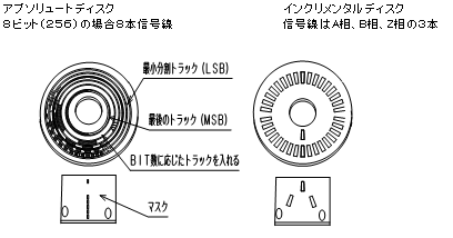
This difference comes from the internal slit-disk structure. Absolute encoders have a unique slit pattern, so each position is assigned an address.
Incremental encoders have a repeating slit pattern and output pulses according to the amount and direction of rotation.
Incremental Encoder
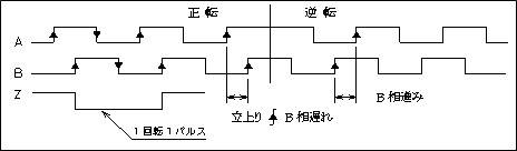
The encoder output is a repeating high and low pulse waveform. Common configurations include single-phase output, two-phase A/B output, and A/B output with a Z-phase origin signal.
The number of pulses per revolution is partly determined by the size of the rotating slit disk. In general, a larger encoder diameter can support a higher maximum resolution.
Rotation can be measured by adding and subtracting pulses. However, the current position is lost when the power is turned off.
To restore the position, the upper-level controller must detect the Z-phase signal or a mechanical origin and then establish the required count position.
Absolute Encoder
Absolute encoders are available with pure binary, Gray code, BCD, and serial communication outputs.
When the power is turned on, the encoder outputs the address corresponding to its current mechanical position.
With parallel output, the required number of signal lines increases with resolution. For example, an 8-bit encoder with 256 positions requires eight signal lines, excluding the power supply and GND.
Serial communication types reduce the number of signal wires while supporting higher resolution.
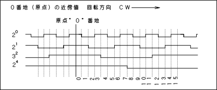
Gray code output
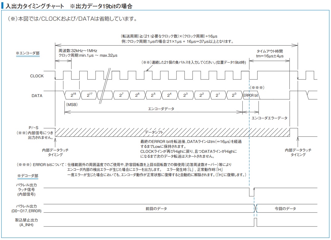
SSI serial communication timing chart
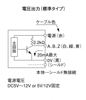
Voltage output
A 2.2 kΩ pull-up resistor is built into the encoder’s internal output circuit. This output is mainly used with 5 V TTL input systems.
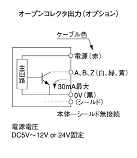
Open collector output
The encoder’s internal output circuit does not include a pull-up resistor. A pull-up resistor must be connected externally.
The encoder cable can generally be extended up to approximately 10 m, depending on the operating conditions.
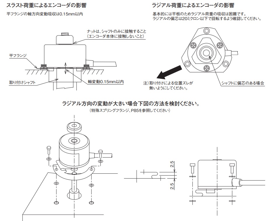
Line driver output
Line driver output is suitable for high-speed response, improved noise resistance, and longer cable distances.
The receiving system must include a compatible line receiver circuit.
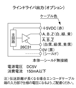
Forward and reverse rotation are identified by the phase difference between the A-phase and B-phase signals.
If the A-phase signal rises before the B-phase signal, the encoder is rotating in one direction. If the B-phase signal rises first, the encoder is rotating in the opposite direction.
The actual definition of clockwise and counterclockwise rotation should be confirmed in the specification for each encoder model.
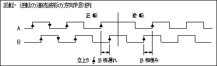
The general mounting procedure is shown below.
1. Attach the spring flange to the encoder
Attach the optional spring flange to the PCD mounting holes on the
encoder base using the supplied flat-head screw, washer A, and
washer B.
2. Insert the encoder onto the measured shaft
Machine a stepped section and male thread on the end of the measured
shaft. Insert the encoder until the end face of the hollow shaft
contacts the stepped surface.
3. Clamp and secure the encoder shaft with a nut
Tighten the nut to clamp the hollow shaft in the thrust direction.
Before fully tightening the nut, lightly rotate the encoder shaft and identify the position with the lowest runout. Then fully tighten the nut.
4. Secure the spring flange to the machine housing
Use the outer mounting holes of the spring flange to secure it to the
machine housing. Screws for mounting the flange to the housing are
not included.
Use a spacer of approximately 1.5 to 2 mm between the spring flange and the housing. The spring flange must not contact the housing, because this would prevent it from functioning correctly.
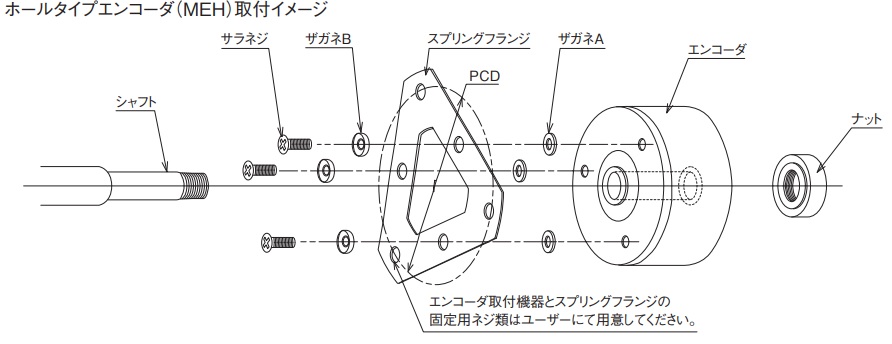
Because the standard spring flange is a flat plate, it has limited ability to absorb radial eccentricity. Keep radial runout during rotation at approximately 20 μm or less.
Special spring flanges are also available for applications with larger radial variation.
The following manufacturers offer counters, converters, interface boards, and other equipment for displaying encoder signals or acquiring encoder data on a computer.
Cocores Inc.
https://cocores.co.jp/
Cocores offers counters for displaying encoder rotation angles and F/V converters for speed conversion. Analog output options suitable for measurement applications are also available.
Interface Corporation
https://www.interface.co.jp/
Interface offers PCI and other interface boards for acquiring encoder signals on a computer, including I/O boards and counter boards.
CONTEC Co., Ltd.
https://www.contec.com/
CONTEC offers counter units, computer interface boards, and USB devices for acquiring encoder signals.
M-System Co., Ltd.
https://www.m-system.co.jp/
M-System offers encoder signal converters, isolators, and display counters. These products are useful when converting encoder signals for connection to upper-level control equipment.
MUTOH Industries Ltd.
https://www.mutoh.co.jp/
MUTOH offers encoders, linear scales, and digital counters with functions such as point output and configurable user settings.
Confirm compatibility and wiring requirements with the equipment manufacturer before use.
Yes. Please provide the manufacturer, model number, and specifications of the encoder currently in use.
Useful information includes:
• Outer diameter and mounting dimensions
• Solid-shaft or hollow-shaft configuration
• Shaft diameter
• Resolution
• Incremental or absolute output
• Output circuit
• Power-supply voltage
• Maximum rotational speed
• Cable length and connector
• Operating environment
MTL can review the information and propose a suitable model from its lineup of approximately 3,000 encoder types.
An equivalent model may not always be completely interchangeable. Mechanical dimensions, wiring, electrical specifications, and control-system compatibility must be checked before replacement.
For example, information about an alternative to the Omron E6C-NN Series is available below.
Incremental encoders may use standard square-wave output or an internal multiplication circuit.
Standard square-wave output
The encoder directly outputs a resolution corresponding to the slit disk installed inside the encoder. The maximum practical resolution is partly limited by the encoder’s outer diameter and internal disk design.
Multiplied output
An internal circuit multiplies the original slit-disk signal to produce a higher output resolution. Depending on the model, multiplication ratios from 2 to 100 may be available.
External x4 counting using the phase relationship between the A-phase and B-phase signals may still be possible after internal multiplication.
Example:
MEH-30-10000PST20
Slit-disk resolution: 10,000 pulses
Internal multiplication: ×20
Encoder output: 200,000 P/R
External A/B x4 counting: 800,000 counts per revolution
The controller’s maximum input frequency must be checked when using a high-resolution encoder at high rotational speed.
An SSI decoder or signal converter is required.
1. MTL decoder board
An MTL DECODER-XXbit board can be used to convert SSI serial output into parallel output.
It supports resolutions up to 20 bits. For a 20-bit configuration, the error bit may not be available.
2. Santest parallel converter
A parallel converter manufactured by Santest Co., Ltd. may also be used. The converter supports resolutions up to 24 bits and has an operating record with MTL encoders.
A/B-phase pulse output is also available as an option.
Product: SSPC Series
Santest SSPC Series
When contacting Santest, mention that Microtech Laboratory Co., Ltd. referred you.
Confirm the SSI clock frequency, bit length, coding format, error-bit configuration, and electrical interface before selecting a converter.
It is possible, but the correct measurement method depends on whether the system needs to measure screw rotation or the actual position of the moving object.
Example conditions:
• A hollow-shaft encoder is mounted directly on a ball screw
• Stage position is calculated from the ball-screw pitch
• Required display resolution: 0.1 mm
• Clean operating environment
• Required accuracy: ±2 mm
• Measurement distance: 2,500 mm
In this configuration, the encoder measures the ball-screw rotation. It does not directly measure the actual linear position of the stage.
Mechanical wear, pitch variation, backlash, coupling error, and uneven screw movement may create a difference between the calculated position and the actual stage position.
Therefore, the following relationship may not remain accurate:
Ball-screw pitch × encoder rotation = actual object position
When actual object position must be measured directly, a wire-type linear encoder such as the MLS-50-540-4000 may be more suitable.
By attaching the measuring wire directly to the moving object, the system can display the object’s actual position without relying only on the ball-screw pitch.
The recommended extension length and cable type depend on the encoder’s output circuit.
Voltage output and open collector output
Recommended wiring length: up to approximately 10 m
Use a shielded cable with a conductor cross-sectional area equivalent to the original encoder cable.
Extending the cable increases capacitance and may increase the rise and fall times of the output waveform. This can reduce the available response frequency and affect the phase relationship between the A-phase and B-phase signals.
The residual output voltage may also increase.
Line driver output
Recommended wiring length: up to approximately 100 m
Use shielded twisted-pair cable and an appropriate line receiver on the receiving side.
At a wiring distance of 100 m, a voltage drop of approximately 1 V may occur, depending on the conductor size and current consumption.
Confirm that the required power-supply voltage is still available at the encoder terminals.
The standard cable length for many MTL products is 1 m. Depending on the model, 3 m, 5 m, and 10 m cable options may also be available.
Consult MTL before requesting a non-standard cable length.
As a general recommendation, use a bending radius of at least six times the encoder cable diameter.
Example for an ME-30P Series cable:
Cable diameter: φ4.2 mm
Recommended minimum bending radius: 4.2 × 6 = 25.2 mm
The cable diameter for each encoder series is listed in the cable section of the applicable specification table or catalog.
This recommendation applies to normal fixed installation. Applications involving continuous cable movement or repeated flexing may require a larger bending radius and a cable designed for continuous-flex operation.
Yes. MTL can issue a calibration certificate, inspection report, and traceability system chart for an additional fee.
Contact MTL in advance to confirm the quotation, applicable products, required documents, and order procedure.
When returning an encoder with a connector attached, also provide an inspection jig or mating connector that can be used for testing.
If an appropriate inspection jig cannot be provided, it may be necessary to remove the connector or cut the cable before inspection. Confirm the required condition with MTL before shipping the encoder.
For additional information, see:
The warranty period and scope for standard catalog products are generally as follows.
Warranty period
Within one year after the start of use and within 1.5 years after delivery.
Warranty scope
If a product failure attributable to MTL occurs within the applicable warranty period, MTL will repair or replace the affected product free of charge.
The warranty generally applies only to the delivered product itself.
Costs associated with removal, installation, replacement work, production interruption, lost profit, or damage to other equipment are generally outside the warranty scope.
The applicable quotation, specification, purchase agreement, and individual product conditions take priority.
Encoder service life cannot be defined by one fixed number because it depends on the product structure, operating environment, rotational speed, bearing load, temperature, vibration, contamination, and energizing time.
The main life-related components are generally the LED and bearings.
Continuous energization and high operating temperatures can gradually reduce LED light output. Bearing life may also be reduced by excessive radial or axial load, shaft misalignment, shock, or vibration.
As a preventive-maintenance reference, inspection, calibration, or replacement after approximately one to two years may be considered in applications where measurement reliability is critical.
However, this is not a universal replacement interval. The appropriate maintenance schedule must be determined according to the actual operating conditions and required reliability.
For calibration inquiries: Contact MTL
As a general reference, MTL recommends a termination resistance of approximately 120 Ω.
Depending on the encoder, cable impedance, cable length, receiving circuit, and signal frequency, adjustment within approximately 100 to 300 Ω may be required.
Common reference values include:
• 120 Ω
• 150 Ω
• 220 Ω
The termination resistor should normally be installed near the receiving end of the signal line.
Confirm the output current capacity of the encoder and the input specifications of the line receiver before selecting the resistor.
For long-distance or high-frequency wiring, check the waveform with an oscilloscope and confirm that reflections, overshoot, ringing, and signal amplitude remain within acceptable limits.