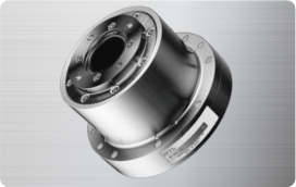
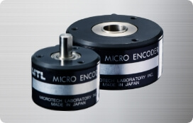
Micro Encoder FAQ

About Micro Encoders
Mainly the optical detection method.
Using an LED as the light source, the encoder detects electrical signals with a light-receiving element based on the light and dark pattern passing through the rotating slit disk.
For reference, other detection methods include magnetic type, Hall element, electrostatic type, electromagnetic induction type, and resolver.
The biggest difference is whether homing is required or not.
An incremental encoder outputs signals from the startup position.
An absolute encoder outputs the address of the startup position.
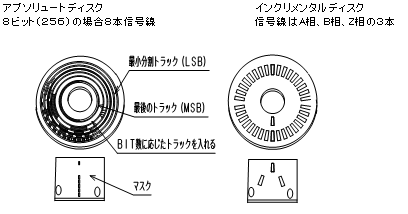
This difference comes from the internal disk slit structure. Absolute encoders have a unique slit pattern, so an address is assigned to each bit.
In contrast, the incremental type has a simple slit pattern and outputs pulses according to the amount of rotation.
Incremental Encoder
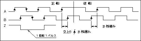
The encoder output signal is a repeating pulse waveform of H and L, and the pulse train is generated continuously. These pulse trains are generally available as single phase, two phase with A phase and B phase, or two phase with A phase and B phase plus the origin phase, Z phase.
The number of pulses per revolution is determined by the size of the rotating slit disk, so the larger the outer diameter, the higher the maximum resolution.
Pulse addition and subtraction according to rotation are possible, but when the power is turned off, the current address is lost. To reproduce the original position, the origin, Z phase or mechanical origin, must first be detected on the upper-level side, and then the specified count address is searched.
Absolute Encoder
Absolute encoders are classified into pure binary output, Gray code output, and BCD output.
When the power is turned on, the encoder outputs the signal of the current address corresponding to the mechanically rotated position.
Because the number of signal lines must match the resolution, higher resolution requires more signal lines. In the case of 8-bit, 256 divisions, eight signal lines are required, excluding power and GND.
Serial communication output types are also available, making both reduced wiring and high resolution possible.
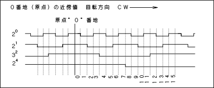
Gray code output
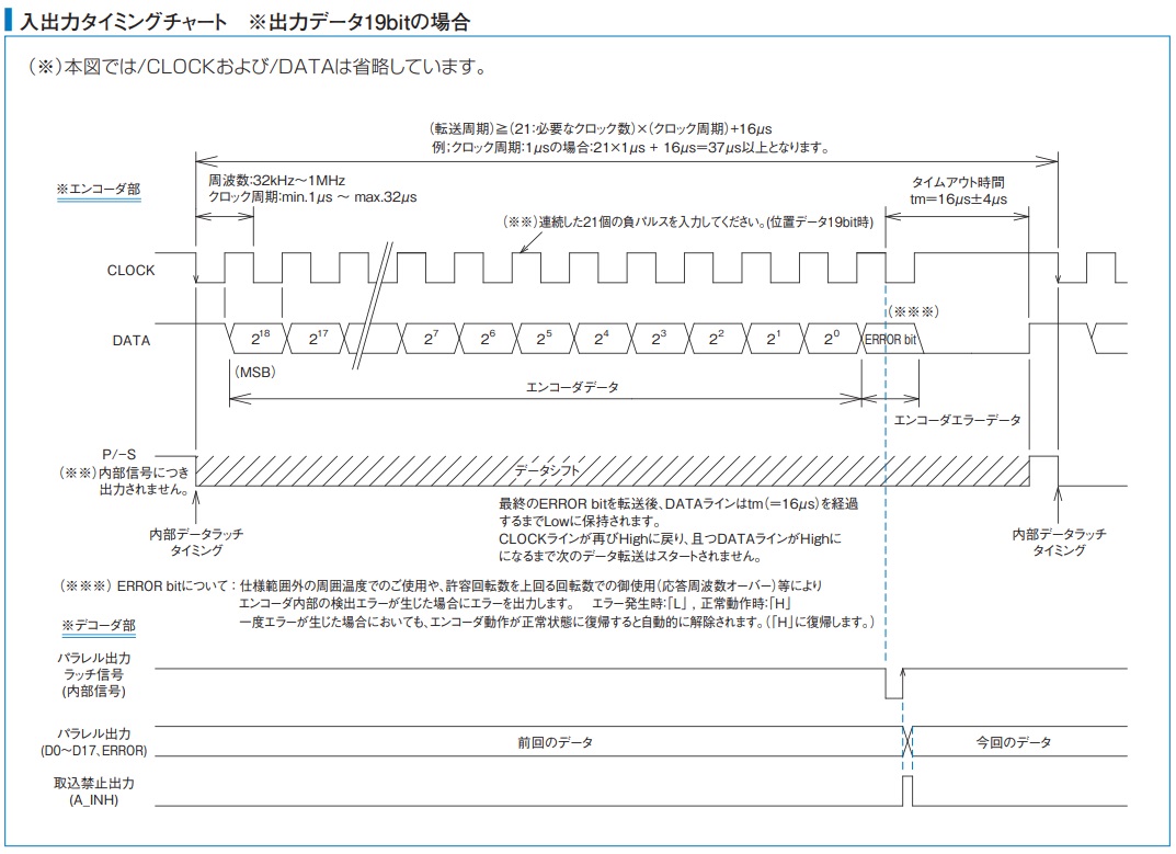
Timing chart for serial communication, SSI format
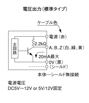
Voltage output type
A 2.2 kΩ pull-up resistor is built into the internal output circuit of the encoder.
It is mainly used as a TTL input type for 5 V systems.
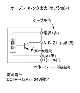
Open collector output
There is no pull-up resistor in the internal output circuit of the encoder.
The pull-up resistor is connected externally. The encoder cable can generally be extended up to about 10 m.
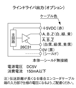
Line driver output
Effective for high-speed response, noise resistance, and cable extension over several tens of meters.
The signal input circuit on the system side must be a line receiver circuit.
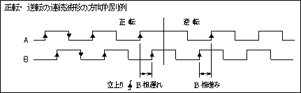
Forward and reverse rotation are identified by the phase difference between A phase and B phase.
If A phase rises first, it is forward rotation. If B phase rises first, it is reverse rotation.
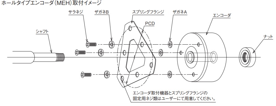
The procedure is shown below.
1. Attach the spring flange to the encoder
Attach the optional spring flange to the PCD mounting holes on the encoder base using the supplied flat-head screw, washer A, and washer B.
2. Insert the encoder onto the measured shaft that has a stepped section and thread machining
Add a stepped section and a male thread to the end of the measured shaft, then insert the encoder so that the end face of the hollow shaft contacts the stepped surface.
3. Clamp and fix the encoder rotating shaft with a nut
Clamp the hollow shaft in the thrust direction by tightening the nut.
Before tightening the nut fully, lightly rotate the encoder shaft and tighten it at the point with the least runout.
4. Fix the spring flange to the machine housing
Finally, use the outer mounting holes of the spring flange to fix it to the machine housing. Screws for fixing it to the housing are not included.
When fixing it to the housing, use a spacer of about 1.5 to 2 mm between the spring flange and the housing so that the spring flange does not touch the housing. Otherwise, the spring action of the flange cannot be maintained.
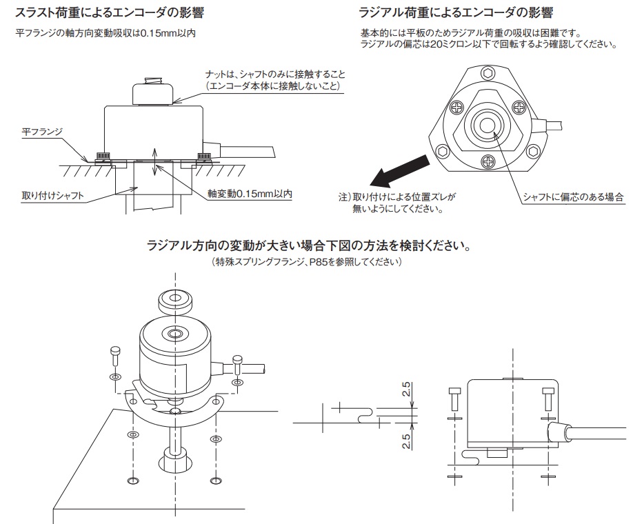
The spring flange is a flat plate, so it is difficult for it to absorb load caused by radial eccentricity. Please make sure the radial eccentricity remains about 20 μm or less during rotation.
If the radial variation is large, we also offer a special spring flange.
The following manufacturers offer various counters and PC boards for signal display and data acquisition to a computer.
● Cocores Inc.
https://cocores.co.jp/
They offer a wide lineup of counters for displaying encoder rotation angle and F/V converters for speed conversion.
Analog output options useful for measurement are also available, and we have many connection records.
● Interface Corporation
http://www.interface.co.jp/index.asp
They offer PCI boards for taking encoder signals into a PC, including I/O boards and counter boards.
● CONTEC Co., Ltd.
https://www.contec.com/jp
They offer counter units for displaying encoder signals, as well as boards and USB units for input to a PC.
● M-System Co., Ltd.
https://www.m-system.co.jp/Japanese/
They offer encoder signal converters, isolators, and display counters. These are useful when converting encoder signals for input to upper-level equipment.
● MUTOH Industries Ltd.
https://www.mutoh.co.jp/products/~deji/index.html
They are a manufacturer of encoders, linear scales, and counters. Their counters are characterized by external outputs such as point output and a wide range of user settings.
Please let us know the manufacturer, model number, and encoder specifications of the unit currently in use.
We can propose a suitable model from our lineup of 3,000 encoder types.
Example: An Omron E6C-NN equivalent is available
here.
There are two types: square wave and multiplied circuit.
• Square wave
The resolution corresponding to the slit disk built into the encoder is output. The upper limit of the resolution is restricted by the outer diameter of the encoder.
• Multiplied circuit
A circuit is built in that can multiply the slit disk resolution by 2 to 100 times, making higher resolution and higher-speed support possible.
Even when a multiplied circuit is installed, external x4 multiplication using the phase difference of A and B phases is still possible.
Example: MEH-30-10000PST20: slit disk 10,000 pulses × multiplied circuit 20 = 200,000 P/R, 800,000 counts after external x4 multiplication.
Please use a decoder or converter.
1. MTL decoder board
By using our decoder board, DECODER-※※bit, it is possible to convert to parallel output.
It is compatible with up to 20 bit. In the case of 20 bit, the error bit cannot be used.
2. Santest parallel converter
A parallel converter made by Santest Co., Ltd. can also be used.
It supports up to 24 bit and has a proven operating record with our products.
A/B phase pulse output is also available as an option.
For details, please contact Santest Co., Ltd. at https://www.santest.co.jp/ja/
When contacting them, it will help if you mention that you were referred by Microtech Laboratory Co., Ltd.
Product name: SSPC Series
https://www.santest.co.jp/ja/product/series/gy_option/sspc-02.php
1. Mount the hollow encoder directly on the ball screw and detect stage position by pitch feed.
Display 0.1 mm, clean environment, accuracy ±2 mm, measurement distance 2,500 mm.
2. At locations with frequent use, wear and unevenness of the screw cause the pitch amount and stage position to shift, meaning there is mechanical error.
Under the above conditions, there is a possibility that ball screw pitch = encoder resolution ≒ measured object position will shift.
By using the wire-type linear encoder MLS-50-540-4000 and attaching a wire hook to the measured object, the actual position of the object can be displayed without being affected by screw pitch.
The allowable extension length and recommended cable vary depending on the output type. Please refer to the following.
Voltage output and open collector output
● Wiring length: maximum 10 m
● Recommended cable: use the same cable as the encoder cable in terms of conductor cross-sectional area and shielding.
● Notes: extension may increase the rise time of the output waveform and reduce the response frequency.
It may also affect the phase difference characteristics of A and B phases and increase the residual output voltage.
Line driver output
● Wiring length: maximum 100 m
● Recommended cable: shielded twisted-pair cable
● Notes: at 100 m, a voltage drop of about 1 V may occur.
Please make sure DC 5 V can still be supplied to the encoder.
Also, use a suitable receiver on the receiving side.
The standard cable length of our products is mainly 1 m, but 3 m, 5 m, and 10 m options are available.
If you want to change the cable length, please consult us before requesting a quotation.
The recommended value is six times the cable diameter used for the encoder.
Example, cable diameter used in the ME-30P Series: φ4.2 mm
Minimum bending radius r = 4.2 × 6 = 25.2 mm
The cable diameter of each series is listed in the “Cable” section of the specification table in the catalog, so please refer to it.
We can issue a calibration certificate, inspection report, and traceability system chart for a fee.
Please contact us if you would like to confirm the quotation, order procedure, or issued documents in advance.
If the encoder you send to us has a connector attached, please also send the inspection jig that mates with the connector.
If there is no inspection jig, please cut the cable and send it to us.
We also have a column article for those who would like to know more about calibration.
The warranty period and scope for products listed in the catalog are as follows.
• Warranty period
Within one year after start of use and within 1.5 years after delivery.
• Warranty scope
If a failure occurs due to our responsibility within the above warranty period, we will repair or replace the product free of charge.
Please note that the warranty applies only to the delivered product itself. Expenses associated with replacement work, such as labor costs, and compensation for damages are outside our responsibility.
Regarding service life, the design life depends on the operating environment and is mainly affected by aging deterioration of the LED or bearings.
As a recommendation, replacement is suggested after two years.
Please note that this is not a universal guideline for all products, since it depends on the operating environment.
It is affected by operating temperature and energizing time. If power is continuously applied, light output may degrade by about 10% over three to five years.
This is still within a range that does not cause any performance issue, but by replacing the unit or requesting calibration after one to two years, highly reliable performance can be maintained.
For calibration requests, click here.
As a reference value, we recommend 120 Ω.
When considering reflection of the signal waveform, please adjust within the range of about 100 to 300 Ω.
Recommended reference values: 120 Ω, 150 Ω, and 220 Ω.
Please note that the appropriate value may vary depending on the product and cable.