Force measurement Direct Drive Motor
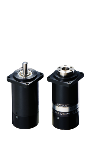
This article introduces a method for detecting contact and measuring indentation stiffness with a direct drive (DD) motor, without using external sensors. Featuring a high-resolution encoder, low friction, and high backdrivability, MTL’s DD motor can function not only as a drive source, but also as a sensing element that detects contact and displacement.
1. Overview
Detecting contact under very small loads and measuring object displacement generally require external devices such as load cells or displacement sensors. However, adding external sensors complicates the mechanical design and can make it more difficult to reduce equipment size and cost.
To address this issue, MTL proposes using the DD motor itself as part of the sensing system.
MTL’s DD motors feature a high-resolution encoder, low friction, and high backdrivability.
Small changes in load at the moment of contact are reflected in the motor current and encoder position in real time. This makes it possible to perform various measurements using the DD motor alone, without adding an external force or displacement sensor.
This article presents three examples of external-sensor-free detection and measurement using a DD motor:
(1) applied force control, (2) contact detection, and (3) indentation stiffness measurement.
2. Measurement Method
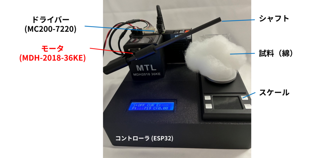
Figure 1 shows the configuration of the demonstration system used for these measurements. The system uses an ultra-compact MDH-2018-36KE DD motor and related components.
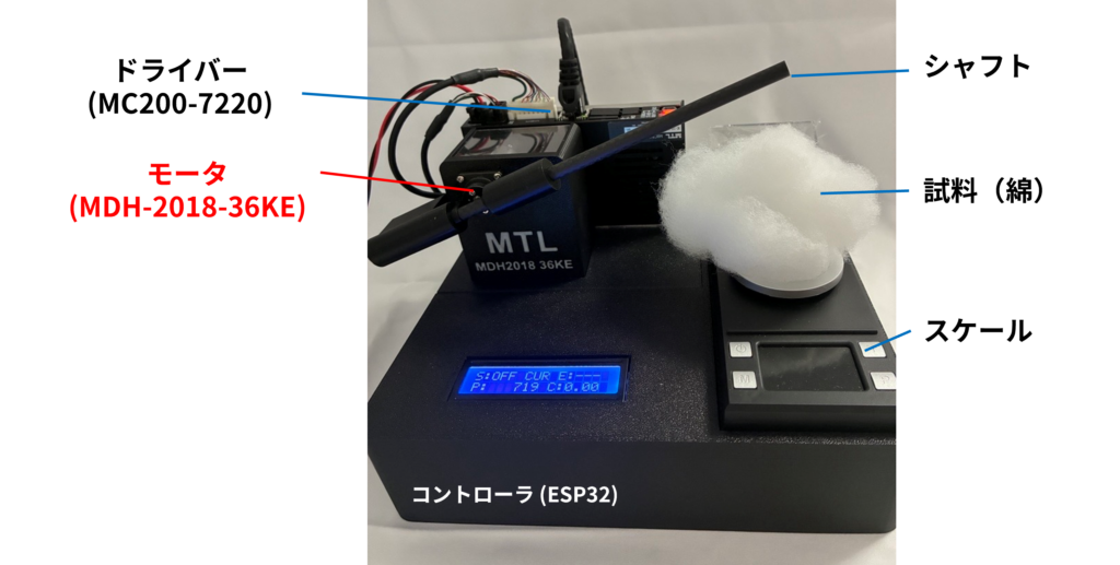
Figure 1. Demonstration system configuration
| MDH-2018-36KE | Compact hollow-shaft direct drive motor | Outer diameter: 21 mm Hollow-shaft diameter: 2.6 mm Resolution: 144,000 counts/rev Peak torque: 0.12 N·m |
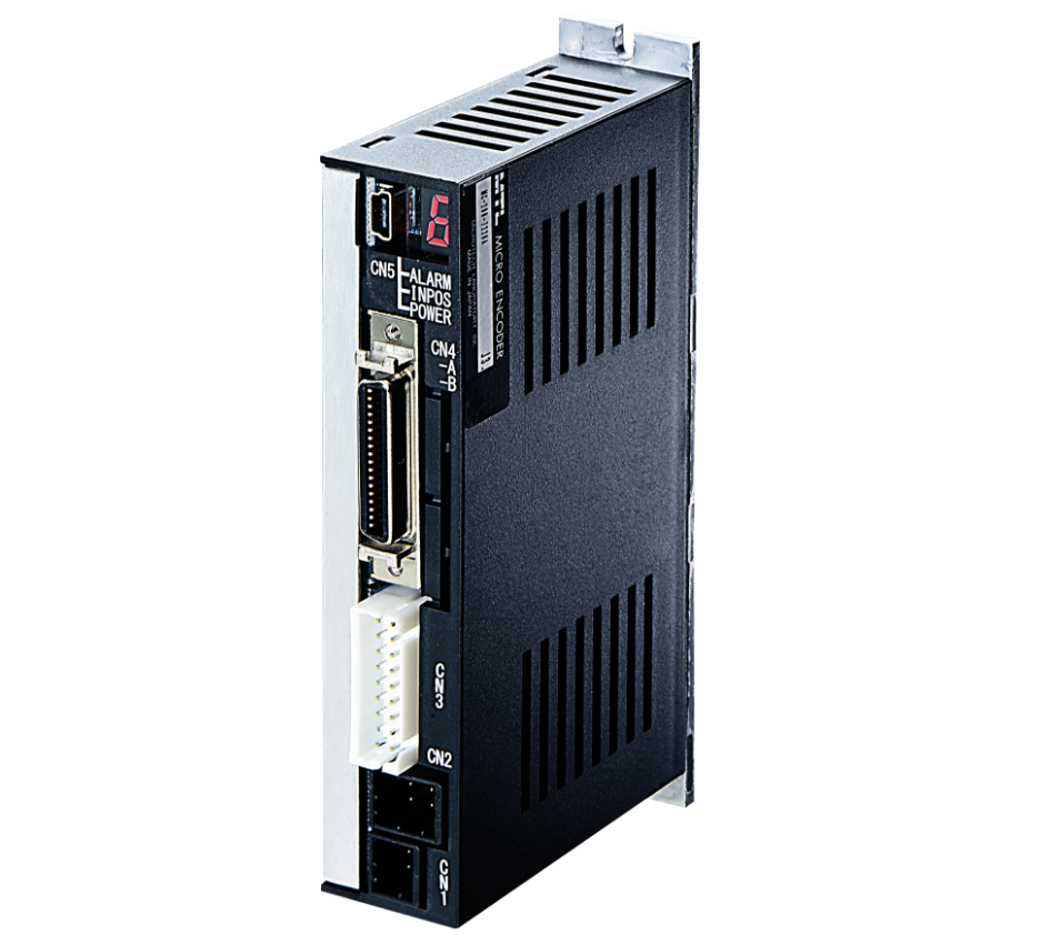
| MC-200-7220D | Compact servo driver with SPI communication | RJ-45 connector supported |
2.1 Applied Force Control
An electronic scale was used to measure the relationship between the force applied at the shaft tip and the motor current.
A calibration equation relating current to force was then derived from the measurement results and used to evaluate the accuracy of the force applied at the shaft tip. The same calibration equation was also used to determine the contact detection thresholds in Section 2.2 and calculate indentation stiffness in Section 2.3.
Calibration equation used to convert current I into force g at the shaft tip:
g: Force at the shaft tip [g]
a, b: Calibration coefficients determined by the least-squares method from the measured I-g relationship
2.2 Contact Detection
(1) Contact Detection During Rotation
The test evaluated whether contact could be detected when a shaft rotating at low speed touched a stationary sample.
Current values recorded under non-contact conditions were used as the reference range. Contact was detected when the measured current moved outside this range.
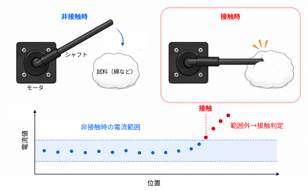
Figure 2. Principle of contact detection during shaft rotation
(2) Contact Detection While Stationary
The test evaluated whether contact could be detected when a sample touched a shaft being held stationary.
Current and encoder position values recorded under non-contact conditions were used as the reference ranges. Contact was detected when either measured value moved outside its reference range.
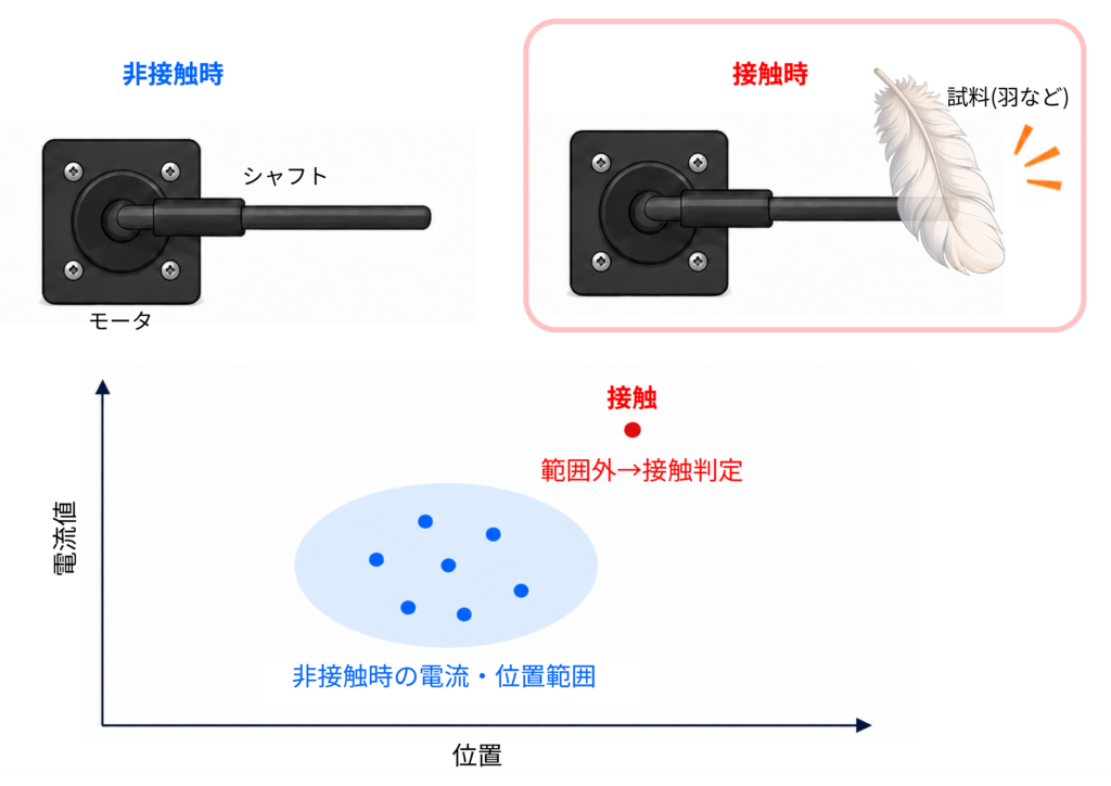
Figure 3. Principle of contact detection while the shaft is stationary
2.3 Indentation Stiffness Measurement
Indentation stiffness was calculated from the applied force and indentation depth when the shaft tip was pressed into a sample using a constant current command.
The applied force was obtained from the motor current, while the indentation depth was calculated from the change in encoder position.
Because no absolute hardness calibration was performed, K does not represent absolute material hardness. It is an apparent indentation stiffness value intended for relative comparison between samples measured under the same conditions.
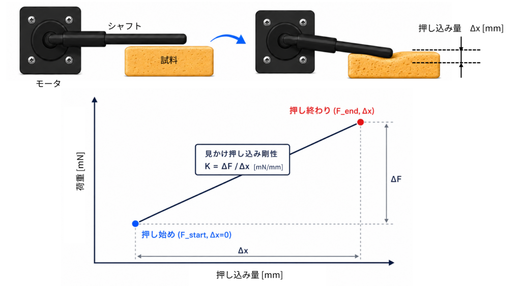
Figure 4. Calculation of apparent indentation stiffness K
Equation used to calculate apparent indentation stiffness K from the difference between the initial and final forces and the indentation depth:
Fstart, Fend: Applied force at the start and end of indentation [mN], converted from current using the calibration equation in Section 2.1
Δx: Indentation depth [mm], converted from the change in encoder position
3. Measurement Results
3.1 Applied Force Control
Figure 5 shows the relationship between the force applied at the shaft tip and the motor current measured using the MDH-2018-36KE.
Video 1 shows the system applying a specified target force at the shaft tip based on the calibration equation.
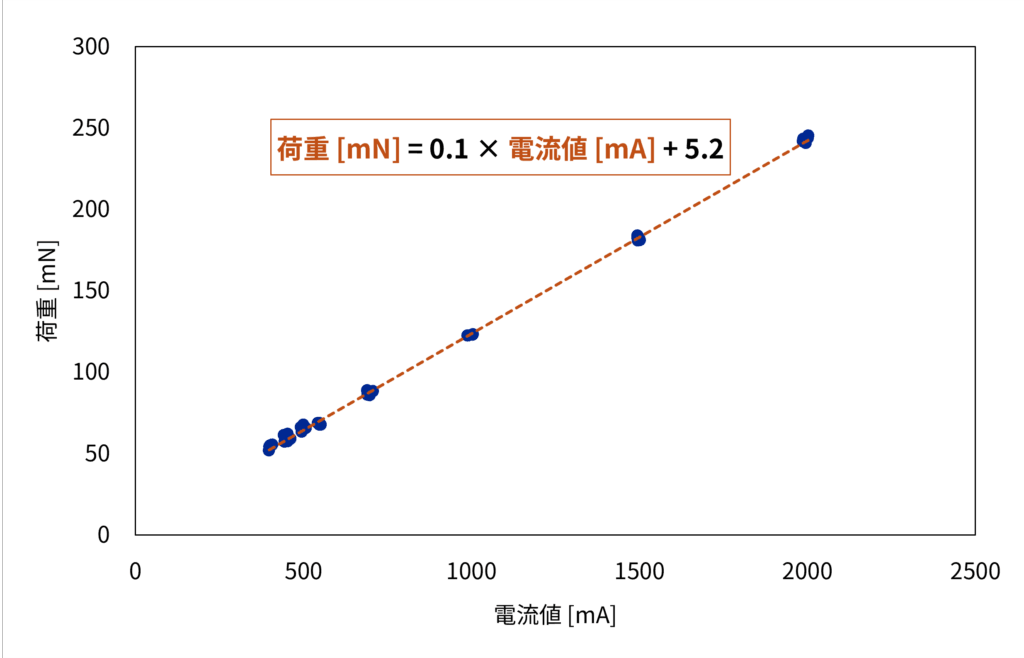
Figure 5. Relationship between shaft-tip force and current for the MDH-2018-36KE
When using the MDH-2018-36KE, the error was approximately 1% to 2% when applying specified forces over a range of approximately 5 to 24 g.
The results confirmed that small forces can be controlled with high accuracy without using an external force sensor.
Video 1. Applying a user-specified force accurately at the shaft tip
3.2 Contact Detection
(1) Contact Detection During Rotation
As shown in Video 2, the system detected the moment when the rotating shaft contacted the sample, without using an external contact sensor.
With the MDH-2018-36KE, the average current threshold was approximately 150 mA, corresponding to an applied force of approximately 17 mN.
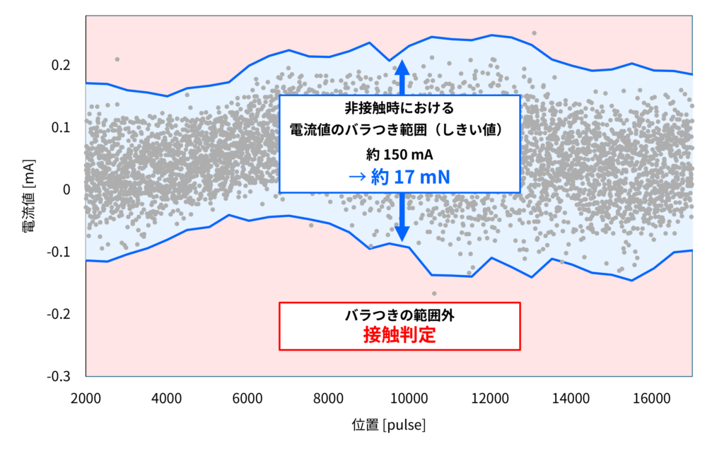
Figure 6. Relationship between current and encoder position during non-contact shaft rotation with the MDH-2018-36KE
Contact sensitivity can be increased by combining current deviation with the change in encoder position within a defined time window, which represents a change in rotational speed.
Video 2. Real-time detection of contact between a shaft rotating at low speed and a stationary cotton sample
(2) Contact Detection While Stationary
As shown in Video 3, the system detected the moment when a sample contacted the shaft while it was being held stationary, without using an external contact sensor.
Because stationary holding eliminates current variation associated with cogging and rotational friction, the detection threshold is lower than during rotation, enabling more sensitive contact detection.
With the MDH-2018-36KE, the detection thresholds were approximately 12 mN for force and 6 μm for displacement. The force threshold was approximately 30% lower than during rotation, allowing the system to detect extremely light contact, such as the touch of a feather.
Video 3. Real-time detection of contact between a stationary shaft and a feather
Relationship Between Motor Model and Detection Threshold
Figure 7 compares the contact detection thresholds of the MDH-2018-36KE and MDH(12)-4006-324KE.
The MDH-2018-36KE has a relatively low equivalent torque constant (Kt), which means it produces less torque per unit of current. As a result, a small force applied at the shaft tip produces a larger and more readily measurable change in current.
Its low current noise also contributes to low detection thresholds of approximately 12 mN while stationary and 17 mN during rotation, enabling highly sensitive contact detection.
In comparison, the MDH(12)-4006-324KE has a higher Kt. The current change produced by an external force is therefore smaller, resulting in higher detection thresholds of approximately 92 mN while stationary and 143 mN during rotation.
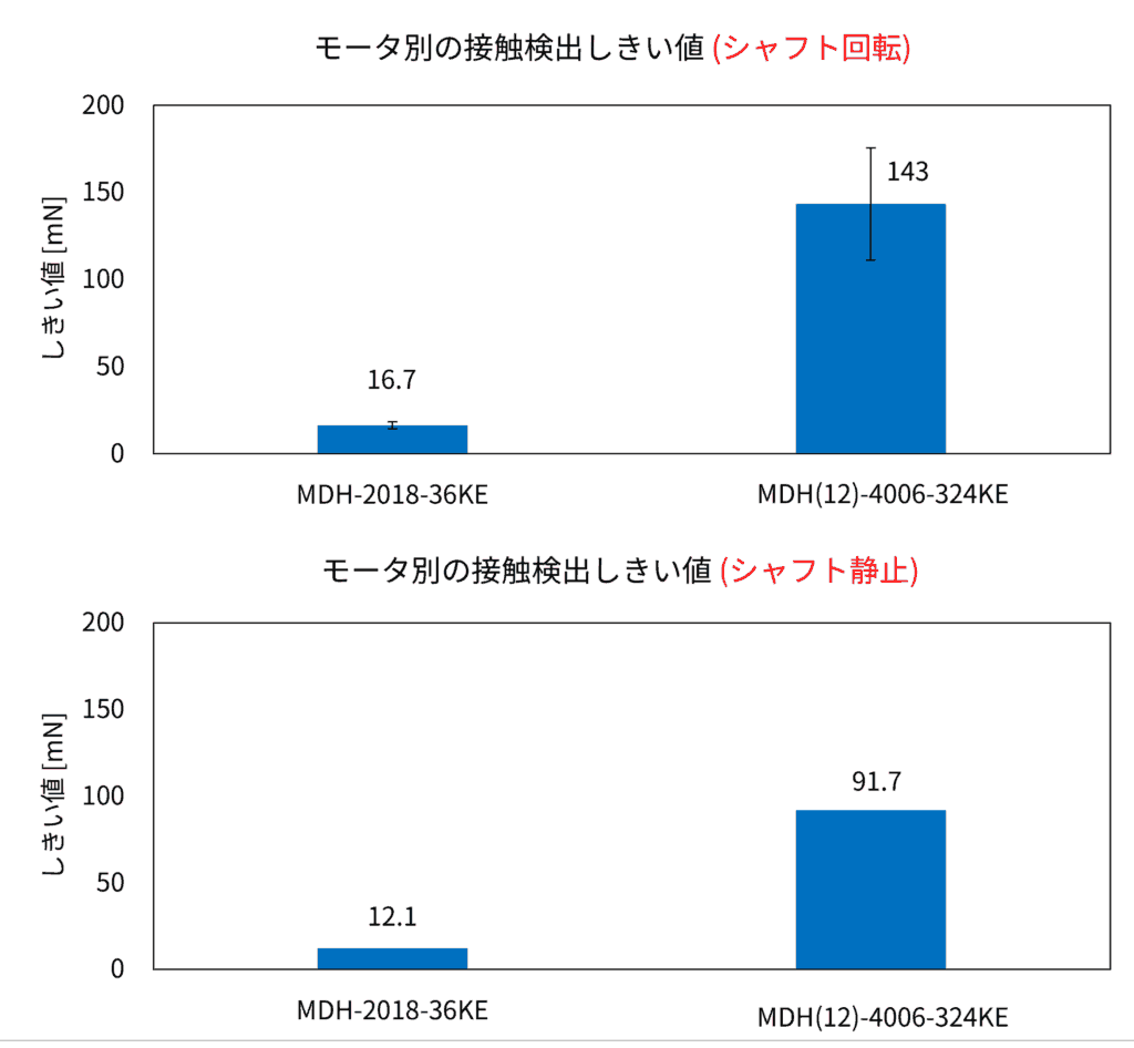
Figure 7. Comparison of contact detection thresholds by motor model: MDH-2018-36KE and MDH(12)-4006-324KE
3.3 Indentation Stiffness Measurement
As shown in Video 4, the apparent indentation stiffness of soft samples such as sponges could be measured and compared quantitatively.
Because sample softness can be compared without adding an external sensor, this method may be applied to pass/fail inspection in production, quality control, and research and development processes.
Video 4. Measuring and comparing the indentation stiffness of sponge samples with different levels of softness
3.4 Summary of Representative Results
Table 1 summarizes the measurement results obtained under representative conditions using the MDH-2018-36KE.
| Evaluation Item | Representative Result |
| Applied force control | Approx. 1% to 2% error, force range: approx. 50 mN and above |
| Contact detection during rotation | Approx. 17 mN |
| Contact detection while stationary | Force: approx. 12 mN Displacement: approx. 6 μm, converted using shaft lever length L = 140 mm |
4. Application Examples
- Gripping-force control for robot hands
Contact detection and force estimation for handling eggs, fruit, and other delicate objects without damage. This approach can also support tactile-sensor-free robot hand designs. - Connector insertion and assembly
Current changes at the moment of contact can be monitored to detect misalignment and help prevent connectors from being inserted at an angle. - Contact confirmation for semiconductor and electronic components
External-sensor-free contact detection can be applied to probe contact confirmation, PCB inspection, and similar processes. - Stiffness evaluation of sponges, rubber, and other materials
The method can support external-sensor-free stiffness inspection and automated pass/fail inspection, including package seal integrity checks. - Following pipes and curved surfaces
Constant torque output and high backdrivability enable controlled pressing against a surface for processes such as polishing and cleaning.
5. Summary
MTL’s DD motors can be used not only as drive sources, but also as sensing elements that detect contact and displacement, including contact detection and apparent indentation stiffness measurement.
Because no external force or displacement sensor is required, this approach can help reduce equipment size and cost while improving maintainability.