Wafer Lifter Detection Using Motor Current Monitoring
Lifter Mechanism and Abnormality Detection
During wafer transfer, the wafer can occasionally stick to the table at the moment it is lifted.
Without adding a separate sensor, changes in motor current alone can be used to identify this abnormal condition. This article explains how the lifter operates and how motor current monitoring can detect wafer sticking, supported by diagrams.
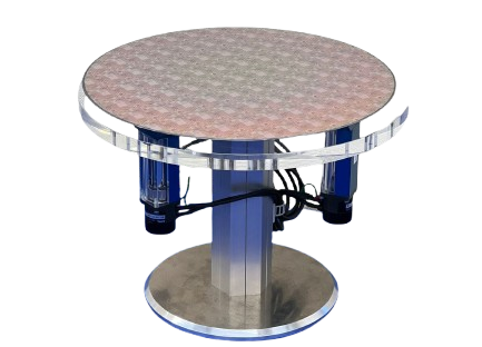
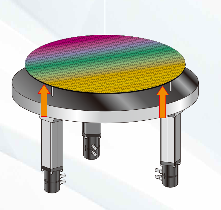
Lifter Structure: Fixed Table and Three Moving Pins
The table remains stationary while only the three lifter pins move up and down in synchronization. Each pin is driven by a DD motor and lead screw. The pins rise through the table and lift the wafer.

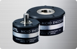
Motor Used
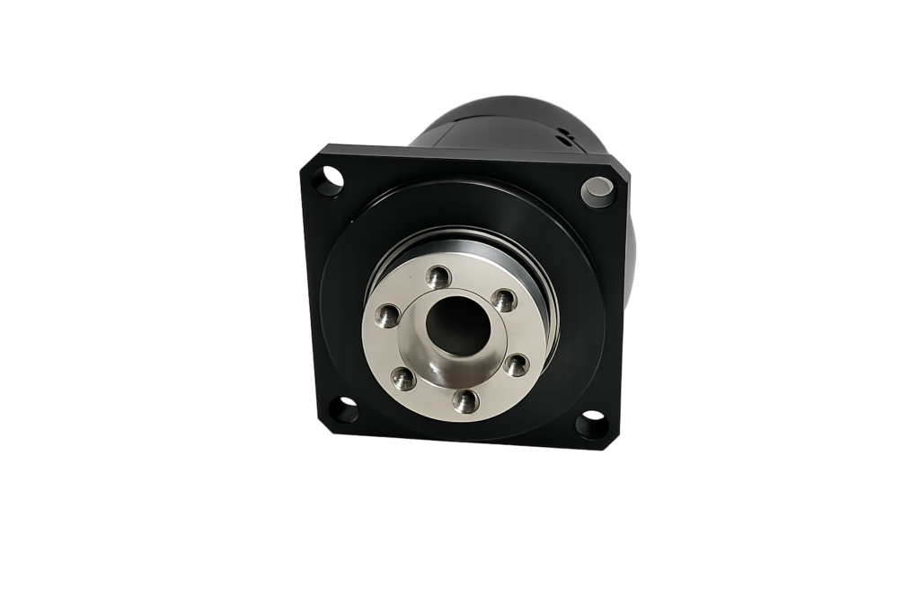
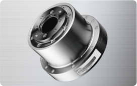
| MDH(6)-3018-108KE | Compact direct drive motor with a large hollow shaft | Outer diameter: 30 mm Hollow-shaft diameter: 6 mm | Resolution: 324,000 counts/rev Peak torque: 0.4 N·m |
What Changes Between Normal and Abnormal Operation?
The table remains fixed while the three pins extend through it to lift the wafer. During normal operation, the sequence progresses from (1) the lowered position to (2) upward movement and then (3) the fully raised position. During abnormal operation, the wafer does not separate from the table, and the pins continue pushing against it, creating excessive load.

The condition in which “the pins continue pushing even though the wafer does not rise” is the key abnormality indicator. The additional force on the pins causes the drive motor current to increase.
Why Motor Current Reveals Wafer Sticking
When wafer sticking occurs, the pins continue pushing against the wafer and place additional load on the motors. As motor load increases, motor current also increases. This relationship makes it possible to detect the abnormal condition without adding a separate sensor. The motor current for each pin is monitored in real time.
Motor Current Noise Filtering Using EWMA
Motor current contains small fluctuations and spike noise while the motor is operating. Comparing the raw current directly with the threshold can cause false detection from a momentary noise spike. To prevent this, the system uses the Exponentially Weighted Moving Average (EWMA).
| Symbol | Description |
| EWMAn | The filtered current value calculated for the current sample. This output is used for abnormality detection. |
| In | The raw motor-current value acquired in real time for the current sample. |
| EWMAn−1 | The previously calculated filtered value, which retains the historical trend. |
| α | The smoothing factor, with a value between 0 and 1. It determines the balance between response speed and noise immunity. |
By continuously combining the latest sample with the historical value at a fixed ratio, EWMA suppresses momentary spikes while reliably capturing the sustained load increase caused by wafer sticking.
Effect of the Smoothing Factor α
Large α, close to 1
The latest measured value In has a stronger influence. The response is faster, but the signal is more sensitive to noise.
Small α, close to 0
The historical average has a stronger influence. The waveform is smoother, but its response to sudden changes is slightly slower.
Wafer Sticking Detection Process Flow
Wafer sticking is detected only when the EWMA-filtered value exceeds the specified threshold, and the system then safely stops all axes. Momentary noise does not stop the machine, which helps prevent nuisance stops while reliably detecting actual abnormal conditions.
Detectable Abnormalities and System Benefits
Examples of Detectable Abnormalities
- Wafer sticking
- Wafer jamming
- Mechanical interference of the lifter pins
- Abnormal friction
- Pin seizure or operating failure
System Benefits
- Simple configuration without additional sensors
- Reduced risk of wafer damage
- Earlier detection of transfer abnormalities
- Improved equipment safety and reliability
Summary
The table remains fixed while three lifter pins rise through it to lift the wafer. When the wafer sticks to the table, it does not rise as intended. This places excessive load on the pins and causes the motor current to increase.
By filtering and monitoring the motor current with EWMA, the system can avoid nuisance stops caused by noise while reliably detecting wafer sticking and transfer abnormalities. This supports safer and more reliable wafer handling.